Text
diffractGUI
Here you can see some examples of diffractGUI inputs and results. All the images were analysed using default diffractGUI settings. Only in case of CBED patterns, a pop-up menu
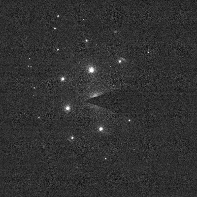
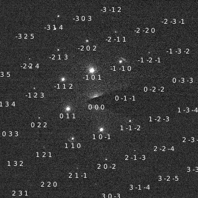
Noisy image
Conditions for the image acquistion are often far from perfect. DiffrractGUI can process even very noisy images. Material: Mg. Zone axis: (1 1 1). Image acquired by Jan Duchoň.
| Input image | Localized pattern | Spots identified |
 |
 |
 |
Nanodiffraction of magnesium
Even a bit atypic diffraction spots can be successfully localized - for example in a nanodiffraction pattern. Material: Mg. Zone axis: (0 0 1). Image acquired by Viera Gärtnerová.
| Input image | Strongest detections | Localized pattern | Spots identified |
 |
 |
 |
 |
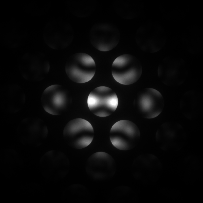
CBED of silicon
DiffractGUI can also detect diffraction disks. Here is an example of CBED pattern taken on sillicon sample. Material: Si. Zone axis: (0 1 1). Image acquired by Martin Němec.
| Input image | Strongest detections | Localized pattern | Spots identified |
 |
 |
 |
 |
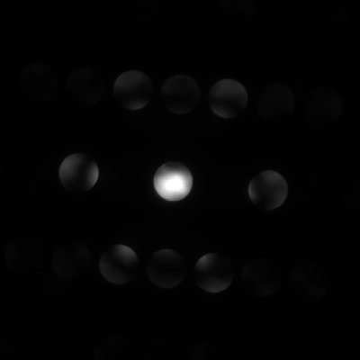
CBED of titanium
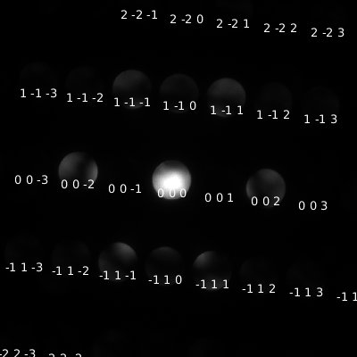
Another example of CBED pattern - this time on alpha-phase titanium. Note that even very dimm disks are correctly localized. Material: Ti Alpha. Zone axis: (0 1 1). Image acquired by Martin Němec.
| Input image | Strongest detections | Localized pattern | Spots identified |
 |
 |
 |
 |
HRTEM - MgZn2
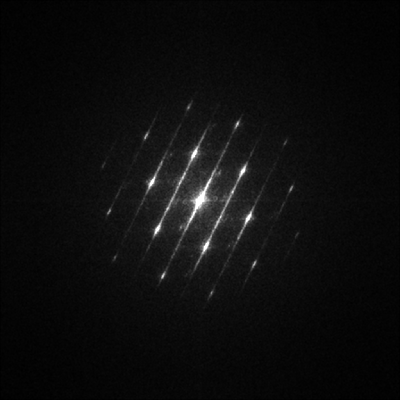
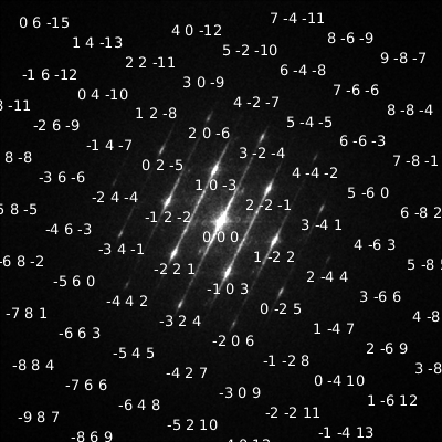
An example of processing HRTEM image. Note, that the spots in the artifficial diffractogram are all significantly blurred in one direction. Material: MgZn2. Zone axis: (6 5 2). Image acquired by Martin Němec.
| HRTEM image | FFT of HRTEM | Localized pattern | Spots identified |
 |
 |
 |
 |
HRTEM - Alpha-phase titanium and delta titanium hydride
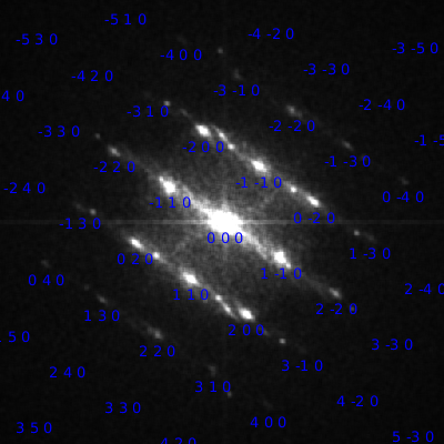
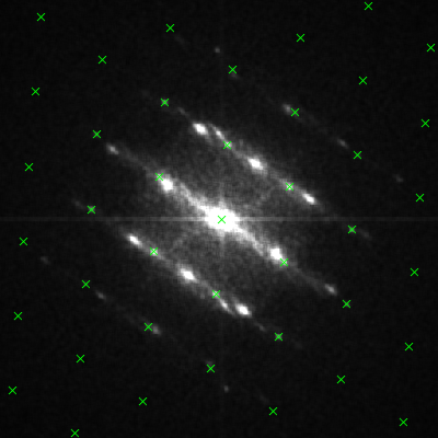
At this HRTEM image, you can see alpha-phase titanium (darker areas in top-left and bottom-right corner) and delta titanium hydride (brighter, central part). Diffraction spots belonging to both materials are visible on the FFT image. Thanks to the Multimodel function, diffractGUI is able to localize both overlapping patterns at once. Material: alpha TI (green) and delta TiH (blue). Zone axis: (0 0 1) (for both materials). Image acquired by Walter Guy.
| HRTEM image | FFT of HRTEM | Localized patterns | Spots identified |
 |
 |
 |
 |
 |
 |
Magnesium twin
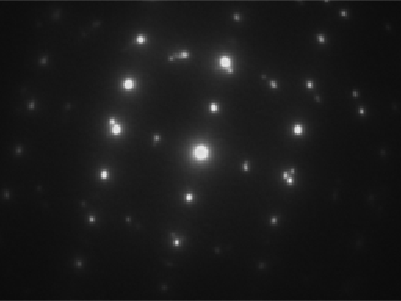
Following image depicts a diffraction of a twin in magnesium. Thanks to the Multimodel function, diffractGUI is able to localize both overlapping patterns at once. Material: Mg (both cases). Zone axis: (1 1 0) (both cases). Image acquired by Jan Duchoň.
| Input image | Localized patterns | Spots identified |
 |
 |
 |
 |
 |
ringGUI
Following pictures depcit some examples of ringGUI inputs and outputs. The analysis procedure was performed with default settings.
Smooth rings
Diffraction rings are very smooth for fine-grained polycrystaline materials. Material: MgO. Image acquired by Viera Gärtnerová.
Spotty rings
In case of a textured material and/or coarser-grained material, the rings can be incomplete. Material: Ti Alpha. Image acquired by Viera Gärtnerová.
| Input image | Overview | Overview | ||||||||||||||||||||||||
 |
 |
 |
||||||||||||||||||||||||
|
|
|
Spotty rings
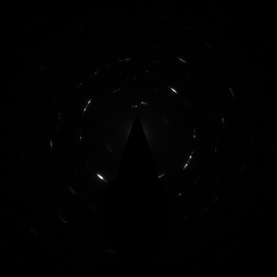
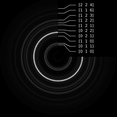
Following image depicts an example of quite spotty diffractogram. Material: Ti Alpha. Image acquired by Viera Gärtnerová.
| Input image | Overview | Overview | ||||||||||||||||||||||||
 |
 |
 |
||||||||||||||||||||||||
|
|
|
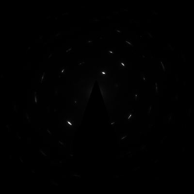
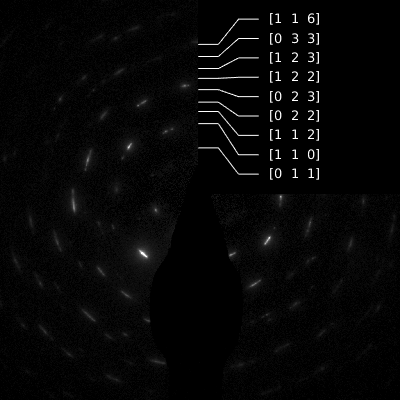
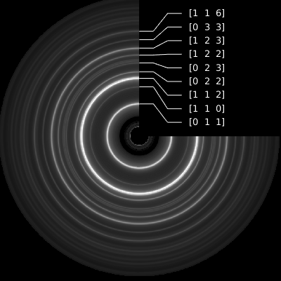
Spotty rings
This is another diffractogram with very spotty rings. However, ringGUI is still able to perform the analysis successfully. Material: Ti Alpha. Image acquired by Viera Gärtnerová.
| Input image | Overview | Overview | ||||||||||||||||||||||||
 |
 |
 |
||||||||||||||||||||||||
|
|
|
