FiDoCNC
a circuit board manufacturing robot
Introduction
I often need to make printed circuit boards for some electronic project; often I find out soon that I need to make another one for major changes. In order to simplify the manufacturing process (to avoid inconvenient etching or long waiting for a PCB printing shop), I built a robot which makes the PCBs almost automatically. It uses a sharp tip of a drill bit to remove the copper from the paths between the connections, so the results are slightly similar to those from etching, but the process is much simpler. It also cuts out the board after it is done and it can drill 0.8 mm holes where needed.
As with other projects, I had in mind to adapt the design so that other people can profit from it, either by building the same machine or by getting inspiration from my experience. One of the main objectives was to employ material that is relatively cheap and easy to obtain so that this project may be useful around the world.


The robot on a wall; a detail of the head
Naturally, the robot can do much more than milling a PCB. I would like to try milling 3-D sculptures (e. g. 3-D maps of mountains), but I am too occupied at work.
Mechanics
There are many similar projects on the web, as a three-axis machining robot is basically quite easy to make and for a hobbyist it is both an amusing toy and a valuable help. One of the most notable is the RepRap project. However, I decided to design the mechanics on my own, as I needed more precise and stiff construction than the RepRaps that I have seen had.
During the design I held the concept of stiffness by geometry (rather than by a massive block of metal), trying to build everything from triangles. This resulted in quite a light construction from aluminium L-profiles, weighting about 4 kg. All linear guides are made of common "607" bearings and steel rods, the three-axis movement is provided by stepping motors with a belt. Almost everything is mounted using M3 or M4 screws, so that any part of the robot may be replaced. The whole mechanics of the robot was built in a common garage workshop, material for under 100 Euro and up to three weeks of work.
Thanks to minimum static friction and microstepping, the repeatability of position is around 0.1 or 0.2 mm. At this scale, it is clear that the construction is somewhat elastic, but it does not cause problems, as the drill bit may not put too much force during PCB milling anyway. The working area is 20x20x15 cm, the overall size of the robot is around 55x60x45 cm.
More description and blueprints will follow
Electronics and firmware
See the FiDoStepper page for details.
Computer software
The download is also at the FiDoStepper age.
The workflow of manufacturing PCBs
I use the GEDA suite for PCB design (i. e. xgsch2pcb, gschem and PCB). It takes some time to learn using these programs so that one can effectively design an useful circuit and there are some annoying things (such as completely differences of behavior of gschem/PCB or stupid autorouter in PCB), but it it is open-source, it outputs data well accessible for PCB milling and I find this software quite prospective.
TODO GEDA + PCB + Patrick Birnzain's pcb2gcode
Example boards made with FiDoCNC
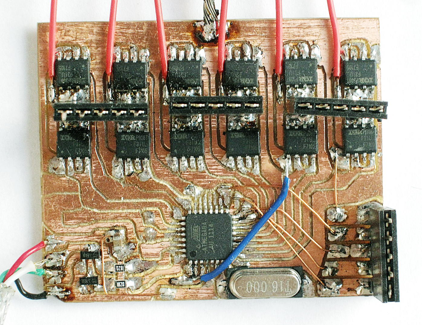

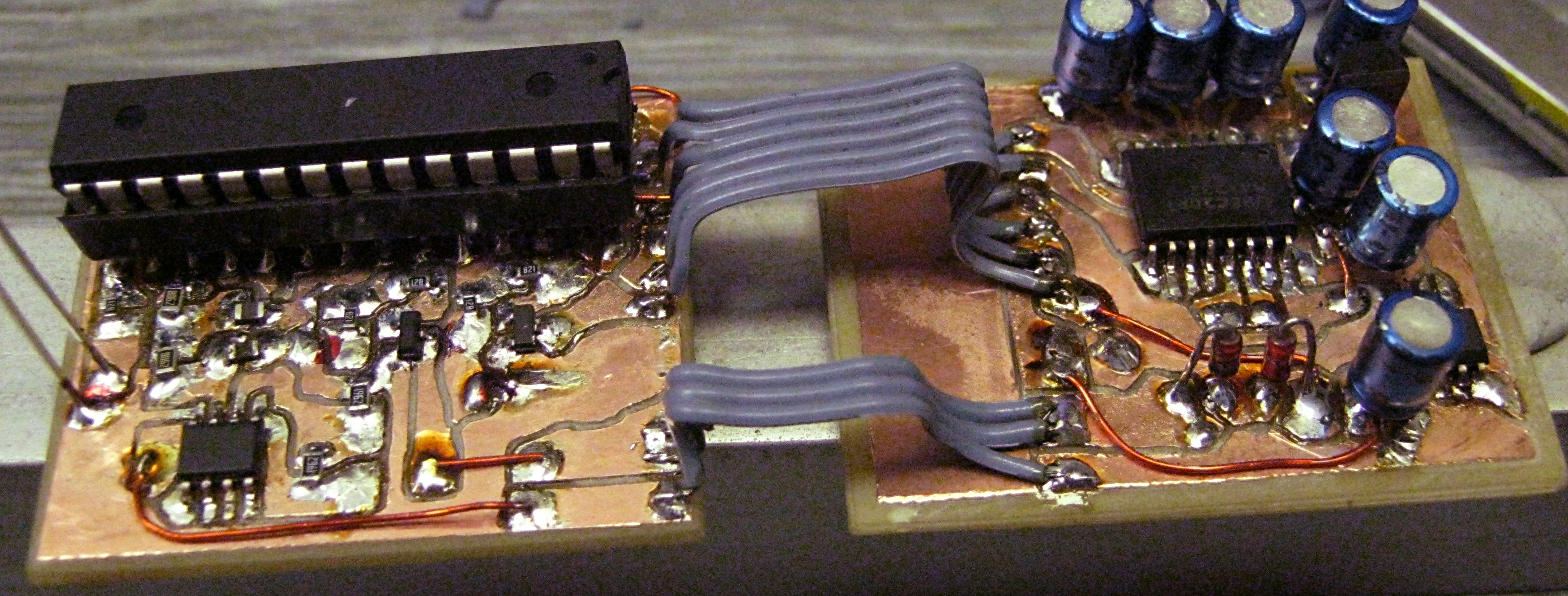

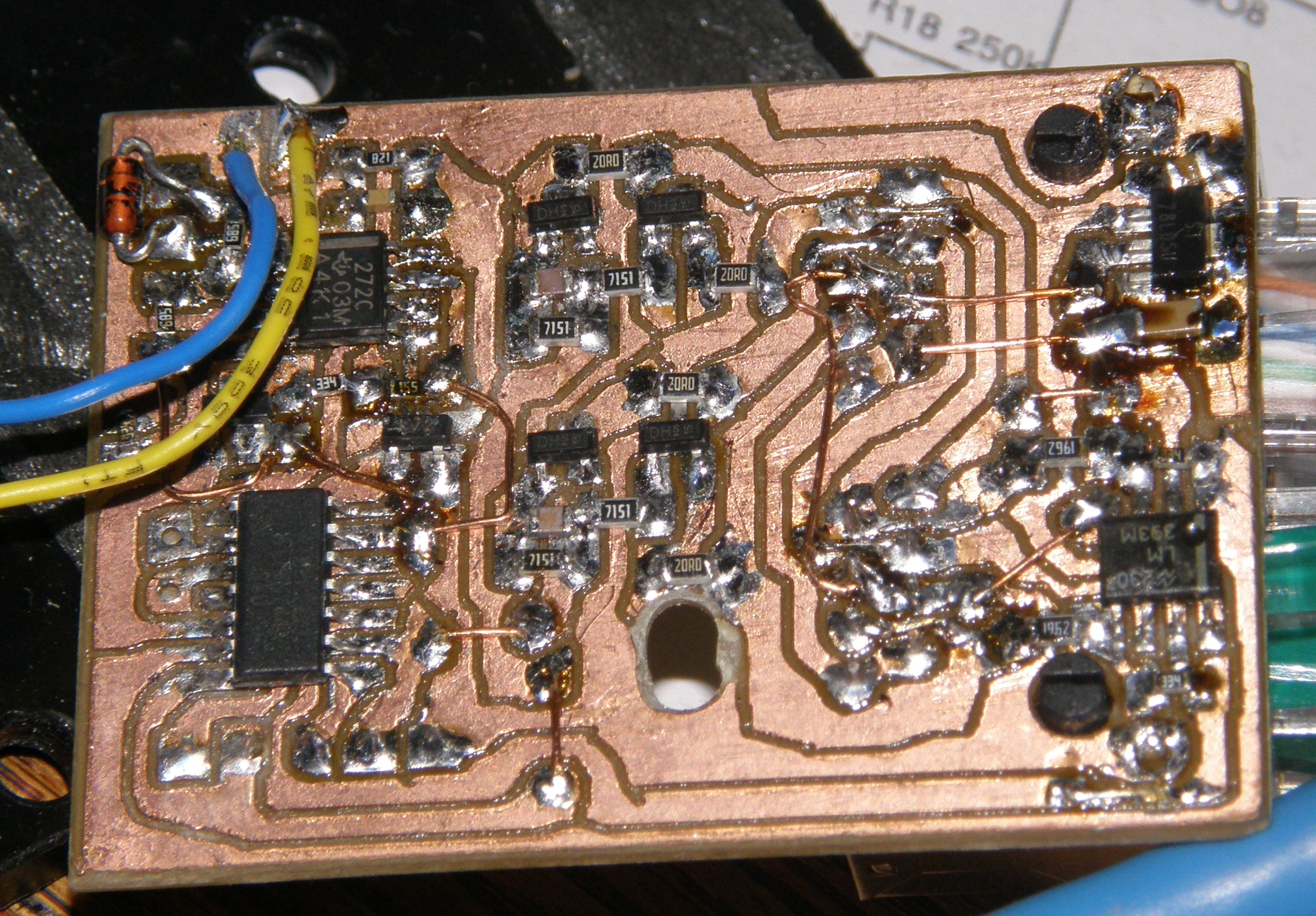

Examples of milled circuits